GD&T BASIC TRAINING
Develop a solid understanding of Geometric Dimensioning & Tolerancing (GD&T) with this comprehensive beginner-level course. Learn core concepts such as part features, feature control frames, material condition modifiers (MMC, LMC, RFS), and virtual condition for ensuring interchangeability in design.The course covers all 14 GD&T symbols, including form, orientation, location, runout, and profile tolerances, along with proper datum selection using the 3-2-1 principle. Practice examples, Calculations and drawing interpretation exercises are also covered.
Develop a solid understanding of Geometric Dimensioning & Tolerancing (GD&T) with this comprehensive beginner-level course. Learn core concepts such as part features, feature control frames, material condition modifiers (MMC, LMC, RFS), and virtual condition for ensuring interchangeability in design.

Duration: 16 Hours
Duration:
16 Hours


Course Content

28 lectures
16h Duration
- What is GD&T? Why use GD&T?
- How does GD&T work?
- Comparison of GD&T with CD&T (Coordinate Dimensioning and Tolerancing)
- What are Part Features?
- Features of Size
- Non-Size Features
- Feature Control Frame (FCF) and its placement
- How to read FCFs?
- Modifier symbols: MMC, LMC, RFS
- When to use MMC, LMC and RFS modifier in design (correct applications)
- Bonus tolerance calculations
- Rule #1 and Rule #2
- Tolerance Zones
- Importance of Virtual condition in designs
- Virtual condition calculations on MMC basis
- Use virtual condition for mating parts as well to design fixed gauges
- 100% interchangeability guarantee in design phase itself by using virtual condition correctly
- Flatness tolerance
- Straightness tolerance
- Circularity Tolerance
- Cylindricity Tolerance
- When to use Form Tolerance?
- Relationship between Rule #1 and form tolerance controls
- Inspection methods to verify form tolerances
- Design recommendation on why to use form tolerances only when required to ensure successful design intent
- What is datum?
- Six Degrees of Freedom
- Datum Reference Frame (Cartesian coordinate system)
- Datum Feature Selection, Functional Hierarchy
- Datum feature identification / placements and interpretation
- Datum plane, datum axis, Datum center plane
- Physical datum feature simulators
- 3-2-1 principle
- Datum feature qualification
- Importance of Datum Precedence
- Select datum features according to the design intent
- How it works? How to apply it?
- Perpendicularity tolerance
- Parallelism tolerance
- Angularity tolerance
- Applied to a planar feature
- Applied to feature of size
- When do we use Orientation Tolerance?
- Datums for Orientation Control
- Inspection methods to verify orientation tolerances
- Difference between parallelism and Flatness
- Class room exercise for orientation tolerance
- Position Tolerance
- How it works? How to apply it?
- Tolerance zone shapes
- Position tolerance for cylindrical features on MMC, LMC and RFS basis
- Detailed table calculations for position tolerance on MMC, LMC and RFS
- Position on Boundary basis for rectangular or oblong slots
- Zero tolerance at MMC basis
- Datums for Position Control
- Inspection methods to verify position tolerances
- Class room exercise for position
- Runout Tolerances
- How it works? How to apply it?
- Circular Runout Tolerance
- Total Run out Tolerance
- Datums for Run out Controls
- Inspection methods to verify runout tolerances
- Profile Tolerances
- How it works? How to apply it?
- Profile of a Line Tolerance
- Profile of a Surface Tolerance
- 4 types of Profile Tolerance Zone
- Bi-lateral
- Unilateral - IN (Un-equally Disposed)
- Unilateral - OUT (Un-equally Disposed)
- Bi-lateral Un-equal (Un-equally Disposed)
- Controlling extent of profile tolerance
- Datums for Profile Controls
- Inspection methods to verify Profile tolerances
- Class room exercise for profile
- Concentricity & Symmetry Tolerances
- How it works? How to apply it?
- Concentricity Tolerance
- Symmetry Tolerance
- Tolerance zone shapes
- Datums for concentricity & symmetry controls
- Inspection methods to verify concentricity & symmetry tolerances
- Why to avoid using Concentricity and Symmetry for small and inexpensive part designs
- Case studies in general and specific to your company / products
- Review existing Your Company drawings
- Discussion on the correct and incorrect use of GD&T on your existing drawings
- GD&T best practices for inspection and manufacturing
- Understand the internal competition between 14 GD&T symbols and select the most appropriate and inexpensive GD&T symbol


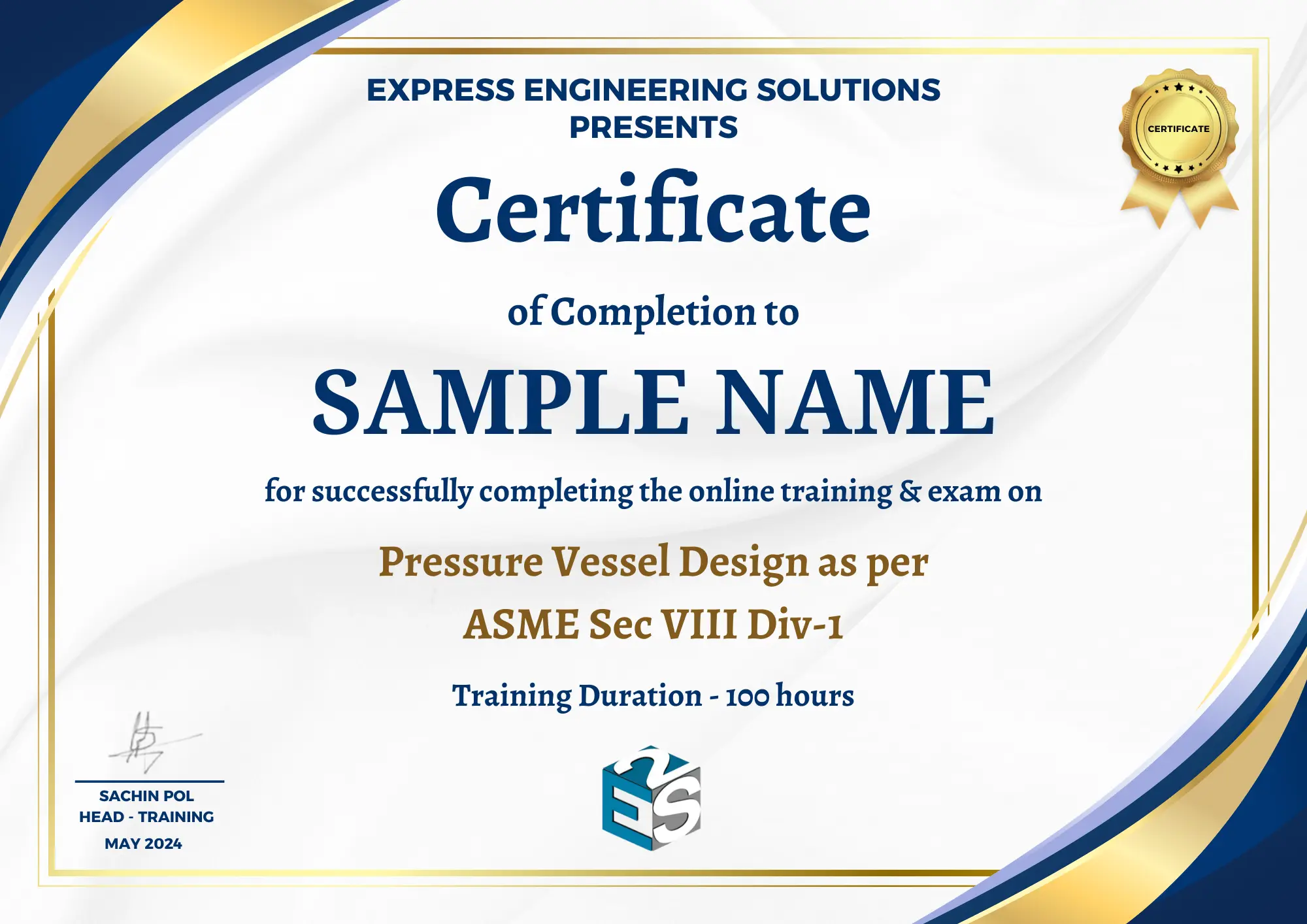
Certificate


Reviews

Sayali Jangam
Experience: 4 Years
L&T Hyrocarbon

It was a great experience during the Pressure Vessel Design training. I have gained very in-depth knowledge about all aspects of Design. It boosted my confidence and as a result the growth in my career has been significant.

Belkacem Kisri
Experience: 5 Years
Bilfinger LTM Industrie SAS
This course is very good. In-depth knowledge about ASME code and Pressure Vessel, Heat Exchanger design & Nozzle Pro FEA. All the concepts are deeply explained. It has helped me enhance my knowledge and confidence.

Elmigdad Omer
Experience: 4 Years
Doha Petroleum Construction Co. Ltd.
My thanks and appreciation to Mr. Sachin Pol for sharing his experience and his effort to make this course effective with technical knowledge and good engineering practices. A great learning experience!

Raghuraman R
Experience: 17 Years
Technip Energies

This is the easiest and quickest way to learn the Code and static design. Very simplified method to make the concepts clear. Calculations are explained in very much detail.

Mangesh Deshmukh
Experience: 14 Years
Toyo

Trainer is technically very perfect and is even a better mentor. The training Program is very organized and cleared all my doubts about static design. Even minute details are taken care of.

Swati Bote
Experience: 10 Years
Worley

I have developed a thorough understanding about the various code requirements and calculations after doing this course. My approach towards Design has become more practical.

Priyanka Burhanpure
Experience: 13 Years
Thermax Ltd.

The content of the course is well-organized and covers all the concepts, code requirements and manual calculations which you need very badly as a Design Engineer. I found this as the only course where you can ask your live project queries.

Arvind Surve
Experience: 22 Years
Alfa Laval
The Quality of teaching is simply excellent! Highly explanatory animations for better understanding, which has made all the concepts very clear.

Mauli Khandekar
Experience: 11 Years
GSEC

The ASME code is difficult to understand and interpret, but the Trainer has made it simple and interesting. The only course in which manual design calculations/problems are taught in-depth.

Nikita Nimbalkar
Experience: 5 Years
TechInt

This is one of the best courses for Static Equipment Design Engineers. It's well-structured, easy to follow, and covers everything—from detailed explanations to manual calculations. A truly comprehensive and valuable course.

Umesh Kulkarni
Experience: 25 Years
Thermax
A very good course. Detailed explanation about the basic concepts. I have gained a lot of knowledge of Pressure Vessel and Heat Exchanger Design. I would definitely recommend this course.

Bhavik Modi
Experience: 10 Years
HLE Glascoat Ltd.

Great learning and experience. Their mentorship has really helped me to enhance my knowledge. This is such a comprehensive online platform for Static Equipment Engineers with manual calculations & Live Q&A sessions.

Brahmananda Mohapatra
Experience: 14 Years
Shreno Engineering Ltd.

I have very much benefited from Live Q&A session as I was able to get the answers to my project queries. It has boosted my confidence and as a result I have successfully faced ASME U-stamp Audit. This training has really transformed my career.

Harshil Thakarar
Experience: 2.5 Years
Meinhardt Group

I have very much benefited from Live Q&A session as I was able to get the answers to my project queries. It has boosted my confidence and as a result I have successfully faced ASME U-stamp Audit. This training has really transformed my career.
This Course Includes:
- 16 hours on-demand videos
- Expert-Curated Content
- Live Q&A Session
- Certificate of completion